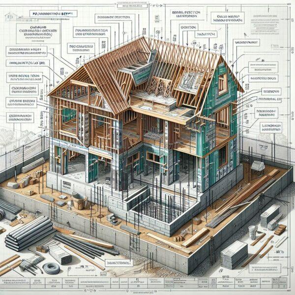
Construction Documents and the Submittal Process

Project Management and Construction Administration – Construction Documents and the Submittal Process

Image Credit: © Lushpix www.fotosearch.com

ARCHITECTURAL ENGINEERING PE EXAM SPECIFICATIONS

Understanding Construction Documents and the
Submittal Process: A Guide for Professionals

In the realm of construction, the importance of precise and detailed documentation cannot be overstated. Construction documents serve as the blueprint for the entire project, encompassing everything from architectural drawings to detailed specifications. Equally critical is the submittal process, which ensures that all materials, equipment, and workmanship meet the project requirements. This guide delves into the intricacies of construction documents and the submittal process, providing professionals with the insights needed to navigate these essential components effectively.

1. The Role of Construction Documents

Construction documents are the cornerstone of any construction project, providing a clear and detailed roadmap for all stakeholders involved. They encompass a variety of documents, each serving a specific purpose. Key types of construction documents include:

  • Architectural Drawings: These are the primary visual representation of the project, detailing dimensions, materials, and the overall design.
  • Specifications: Detailed descriptions of materials, workmanship, and installation methods that complement the drawings.
  • Schedules: Timelines for different phases of the project, ensuring that tasks are completed in a logical sequence.
  • Contracts: Legal agreements between the project owner, contractors, and other parties, outlining roles, responsibilities, and financial terms.
  • Addenda and Change Orders: Documents that capture modifications to the original contract and project scope.

Each of these documents plays a vital role in ensuring that the project is executed as intended, with all parties having a clear understanding of their responsibilities and expectations.

2. The Submittal Process: An Overview

The submittal process is a critical phase in the construction project lifecycle, acting as a quality control mechanism to ensure that all materials and workmanship conform to the project’s specifications. The process typically involves several steps:

  1. Preparation: Subcontractors and suppliers prepare submittals, which include shop drawings, product data, samples, and mock-ups.
  2. Submission: These submittals are then submitted to the general contractor, who reviews them for completeness and compliance with the contract documents.
  3. Review and Approval: The general contractor forwards the submittals to the architect or engineer for further review and approval. This step often involves several rounds of revisions and resubmissions.
  4. Distribution: Once approved, the submittals are distributed to all relevant parties, including subcontractors and suppliers, to proceed with fabrication and installation.

This structured process ensures that all materials and systems used in the project meet the required standards, thereby minimizing the risk of errors and costly rework.

3. Types of Submittals

Submittals can be broadly categorized into several types, each serving a specific purpose in the construction process:

  • Shop Drawings: Detailed drawings that provide a close-up view of components and assemblies, often prepared by subcontractors or suppliers.
  • Product Data: Technical information about products, including manufacturer’s data sheets, installation instructions, and performance characteristics.
  • Samples: Physical examples of materials or products to be used, allowing the architect or engineer to verify quality and compatibility.
  • Mock-ups: Full-scale models or assemblies used to demonstrate the appearance and performance of a particular component or system.

Each type of submittal plays a crucial role in ensuring that the project adheres to the specified quality and performance standards.

4. Best Practices for Managing Construction Documents

Effective management of construction documents is essential for the smooth execution of a project. Here are some best practices to consider:

  • Organization: Maintain a well-organized system for storing and accessing documents. This can be achieved through digital document management systems that allow for easy retrieval and sharing of documents.
  • Version Control: Implement a robust version control system to track changes and ensure that all stakeholders are working with the most current documents.
  • Communication: Foster clear and open communication among all parties involved, ensuring that any changes or updates to the documents are promptly communicated.
  • Documentation: Keep detailed records of all communications, approvals, and changes to provide a clear audit trail throughout the project lifecycle.

5. Best Practices for the Submittal Process

Managing the submittal process efficiently requires attention to detail and effective communication. Here are some best practices to ensure a smooth submittal process:

  • Clear Guidelines: Establish clear guidelines for the preparation and submission of submittals, including formatting, required information, and deadlines.
  • Timely Reviews: Ensure that reviews and approvals are conducted promptly to avoid delays in the project schedule.
  • Collaborative Approach: Encourage collaboration between all parties involved in the review process to address any issues or concerns quickly.
  • Tracking and Follow-up: Use tracking systems to monitor the status of submittals and follow up on pending approvals to keep the process moving forward.

6. Common Challenges and Solutions

The construction document and submittal process can be fraught with challenges. Here are some common issues and their potential solutions:

  • Incomplete or Incorrect Submittals: Ensure that subcontractors and suppliers are well-informed about the requirements and provide training if necessary. Implement a thorough review process to catch errors early.
  • Delays in Review and Approval: Set realistic timelines and maintain regular communication with all parties to expedite the review process. Consider using software tools to streamline the workflow.
  • Changes and Revisions: Establish a clear protocol for managing changes and ensure that all revisions are documented and communicated to all stakeholders.

7. Case Study: Successful Management of Construction Documents and Submittals

To illustrate the effective management of construction documents and the submittal process, consider the case of a large-scale commercial project.

Project Overview: A 50-story office building in a major metropolitan area, with a project value of $500 million.

Challenges:

  • Coordination among multiple subcontractors and suppliers.
  • Ensuring compliance with strict quality standards and building codes.
  • Managing a tight project schedule.

Solutions Implemented:

  • Digital Document Management System: Implemented a cloud-based document management system to store, organize, and share all construction documents. This allowed for easy access and real-time updates.
  • Clear Submittal Guidelines: Developed comprehensive submittal guidelines, including detailed instructions on the required documentation and submission process.
  • Dedicated Submittal Coordinator: Appointed a dedicated submittal coordinator to oversee the process, ensuring timely reviews and approvals.
  • Regular Progress Meetings: Held regular progress meetings with all stakeholders to address any issues and keep the project on track.

Outcome:

  • Successful coordination among all parties, resulting in timely completion of the project.
  • High-quality workmanship and materials, meeting all specified standards and building codes.
  • Efficient management of the submittal process, minimizing delays and rework.

8. The Future of Construction Documentation and Submittals

The construction industry is continually evolving, and advancements in technology are playing a significant role in shaping the future of construction documentation and the submittal process. Some emerging trends include:

  • Building Information Modeling (BIM): BIM technology allows for the creation of detailed 3D models that integrate all aspects of a construction project, improving collaboration and reducing errors.
  • Digital Twins: The use of digital twins, which are virtual replicas of physical assets, enables real-time monitoring and management of construction projects.
  • Artificial Intelligence (AI): AI can be used to automate the review and approval process, identifying potential issues and ensuring compliance with specifications.
  • Blockchain: Blockchain technology can provide a secure and transparent way to manage and track changes to construction documents, enhancing accountability and reducing the risk of disputes.

As these technologies continue to develop, they hold the potential to significantly improve the efficiency and accuracy of construction documentation and the submittal process.

Conclusion

Construction documents and the submittal process are critical components of any construction project, serving as the foundation for successful project execution. By understanding the types of documents involved, the steps in the submittal process, and best practices for managing both, professionals can ensure that their projects are completed on time, within budget, and to the highest quality standards. As the industry continues to evolve, embracing new technologies and approaches will be key to staying ahead and achieving success in the complex and demanding world of construction.

Let us know if there is anything we can do to help you prepare for the exam.


Construction Documents and the Submittal Process

Architectural Engineering PE Exam Resources
NCEES
Contact Us

Copyright©  All Rights Reserved

EngineeringDesignResources.com prohibits the use or reproduction of this material by any means, graphic, electronic, or mechanical, except in the case of brief quotations embodied in critical articles and reviews. This includes photocopying, recording, taping, or by any information storage retrieval system.

Due to the dynamic nature of the Internet, web addresses or links in these materials may have changed.

Any resemblance in the images in this material to actual people or locations is merely coincidental. EngineeringDesignResources.com prohibits reprinting, copying, changing, reproducing, publishing, uploading, posting, transmitting, or using in any other manner images in this material.

Branch Circuit And Feeder Conductor Sizing

Electrical Systems – Branch Circuit And Feeder Conductor Sizing

Branch Circuit And Feeder Conductor Sizing
ARCHITECTURAL ENGINEERING PE EXAM SPECIFICATIONS

Electrical Branch Circuit Sizing and Feeder Conductor Sizing

Electrical systems are the backbone of modern infrastructure, and proper sizing of branch circuits and feeder conductors is essential for safety, efficiency, and reliability. This guide will delve into the intricacies of electrical branch circuit sizing and electrical feeder conductor sizing, providing a thorough understanding for professional electricians, engineers, and technical professionals.

Understanding Electrical Branch Circuits

Definition:

An electrical branch circuit is the portion of wiring that extends from the final overcurrent protective device (such as a breaker) to the outlets and devices it supplies. Properly sizing these circuits ensures that the wiring can safely handle the load without overheating or causing a fire hazard.

Steps to Size a Branch Circuit

  1. Determine the Load:
    • Identify all the electrical devices and appliances on the circuit.
    • Calculate the total load in amperes (A) or watts (W).
  2. Voltage Consideration:
    • Most residential circuits operate at 120V or 240V. Commercial and industrial settings might use different voltages.
    • Ensure the load voltage matches the circuit voltage.
  3. Continuous and Non-Continuous Loads:
    • Continuous loads run for three hours or more. According to the NEC, these should be rated at 125% of the continuous load.
    • Non-continuous loads are rated at 100%.
  4. Select the Correct Wire Size:
    • Based on the total load and voltage, select the appropriate wire size from the NEC wire sizing charts.
    • Consider the material of the wire (copper vs. aluminum) as they have different ampacity ratings.
  5. Overcurrent Protection:
    • Select the appropriate circuit breaker or fuse size to protect the wiring.
    • Ensure the overcurrent protection device is rated higher than the calculated load but within the wire’s ampacity rating.

Example: Sizing a Branch Circuit for a Residential Kitchen

  1. Identify the Load:
    • Refrigerator: 6A
    • Microwave: 10A
    • Lighting: 4A
    • Total load = 20A
  2. Voltage:
    • 120V circuit
  3. Continuous Load:
    • Assume the refrigerator and microwave run continuously.
    • Continuous load calculation: 16A * 1.25 = 20A
  4. Select Wire Size:
    • According to NEC Table 310.16, a 12 AWG copper wire is rated for 20A at 60°C.
  5. Overcurrent Protection:
    • Use a 20A breaker to match the wire size.

Understanding Electrical Feeder Conductors

Definition:

Feeder conductors carry electrical power from the service equipment (such as the main breaker panel) to a subpanel or distribution point. Proper sizing is crucial to maintain efficiency, voltage drop, and system integrity.

Steps to Size Feeder Conductors

  1. Determine the Total Load:
    • Calculate the total connected load served by the feeder, including all branch circuits.
  2. Load Diversity and Demand Factors:
    • Apply diversity and demand factors based on the type of occupancy and load characteristics.
    • Refer to NEC Article 220 for guidelines on applying these factors.
  3. Voltage Drop Consideration:
    • Feeder conductors should be sized to limit voltage drop to 3% for feeders and branch circuits combined, not exceeding 5%.
  4. Select the Appropriate Conductor Size:
    • Use the NEC tables to determine the conductor size based on ampacity.
    • Factor in environmental conditions, such as ambient temperature and conduit fill.
  5. Overcurrent Protection:
    • Select the appropriate main breaker or fuse size to protect the feeder conductors.
    • Ensure the protection device matches the feeder’s ampacity.

Example: Sizing a Feeder for a Small Commercial Building

  1. Determine the Total Load:
    • Lighting: 2000W
    • HVAC: 4000W
    • Office equipment: 3000W
    • Total load = 9000W at 240V
  2. Load Diversity:
    • Apply a demand factor of 0.8 for commercial lighting and office equipment.
    • Adjusted load: 2000W * 0.8 + 3000W * 0.8 = 1600W + 2400W = 4000W
    • Total adjusted load: 4000W + 4000W (HVAC, no diversity factor) = 8000W
  3. Voltage Drop:
    • Assume a feeder length of 100 feet. The voltage drop calculation needs to be performed to ensure it remains within acceptable limits.
  4. Select Conductor Size:
    • Convert the adjusted load to amperes: 8000W / 240V = 33.33A
    • According to NEC Table 310.16, a 10 AWG copper wire is rated for 35A at 75°C.
  5. Overcurrent Protection:
    • Use a 35A breaker to match the feeder conductor size.

Key Considerations and Best Practices

  1. Code Compliance:
    • Always adhere to the latest National Electrical Code (NEC) requirements.
    • Local amendments and codes should also be considered.
  2. Temperature and Conductor Material:
    • Copper conductors are generally preferred for their higher conductivity and durability.
    • Aluminum conductors are used where cost is a consideration, but they require larger sizes for equivalent ampacity.
  3. Voltage Drop:
    • For long runs, calculate voltage drop meticulously.
    • Use larger conductors if voltage drop exceeds recommended limits.
  4. Future Proofing:
    • Consider potential future expansion when sizing feeders.
    • Installing slightly larger conductors can accommodate increased loads without the need for significant upgrades.
  5. Safety Margins:
    • Err on the side of caution with sizing. Over-sizing conductors slightly can provide additional safety and flexibility.

Practical Tips for Field Application

  • Use Conductor Markings: Always check conductor markings for temperature ratings and material type.
  • Derating Factors: Apply derating factors for conductors installed in conduit with multiple other conductors.
  • Inspection and Testing: Conduct thorough inspections and testing after installation to ensure compliance and performance.

Conclusion

Proper sizing of branch circuits and feeder conductors is a critical aspect of electrical design and installation. By following a systematic approach and adhering to NEC guidelines, professionals can ensure safe, efficient, and reliable electrical systems. Whether in residential, commercial, or industrial settings, attention to detail in electrical sizing translates into long-term safety and operational excellence.


Branch Circuit Sizing

Article 210 –  Branch Circuits not over 1,000 Volts AC, 1,00 Volts DC, Nominal


Feeder Conductor Sizing

Article 215 – Feeders


Branch-Circuit, Feeder, and Service Load Calculations

Article 220 – Branch-Circuit, Feeder, and Service Load Calculations

Table 220.3 Specific-Purpose Calculation References

Article 440 – Air-Conditioning and Refrigerator Equipment

Part IV – Circuit Conductors

Article 460 – Capacitors

460.8 – Conductors

Article 427 – Fixed Electric Heating Equipment for Pipelines and Vessels

427.4 – Continuous Load

Article 424 – Fixed Electric Space-Heating Equipment

424.4 – Branch Circuits

Article 426 – Fixed Outdoor Electric Deicing and Snow-Melting Equipment

426.4 – Continuous Load

Article 425 – Fixed Resistance and Electrode Industrial Process Heating Equipment

425.4 – Branch Circuits

Article 430 – Motors, Motor Circuits, and Controllers

430.26 – Feeder Demand Factors

430.25 – Multimotor and Combination-Load Equipment

430.24 – Several Motors or AC Motors and Other Load(s)

Article 235 – Branch-Circuits, Feeders, and Services Over 1,000 Volts AC, 1,500 Volts DC, Nominal

235.19 – Conductors — Minimum Ampacity and Size

Article 215 – Over 1,000 Volt Feeder Calculations

215.2(B) – Minimum Rating and Size/Grounded Conductor

Article 455 – Phase Converters

455.6 – Conductors

Article 422 – Appliances

422.11 – Overcurrent Protection

Let us know if there is anything we can do to help you prepare for the exam.


Branch Circuit And
Feeder Conductor Sizing

Architectural Engineering PE Exam Resources
NCEES
Contact Us

Copyright©  All Rights Reserved

EngineeringDesignResources.com prohibits the use or reproduction of this material by any means, graphic, electronic, or mechanical, except in the case of brief quotations embodied in critical articles and reviews. This includes photocopying, recording, taping, or by any information storage retrieval system.

Due to the dynamic nature of the Internet, web addresses or links in these materials may have changed.

Any resemblance in the images in this material to actual people or locations is merely coincidental. EngineeringDesignResources.com prohibits reprinting, copying, changing, reproducing, publishing, uploading, posting, transmitting, or using in any other manner images in this material.

Building Envelope Analysis For Integrity And Efficiency

Building Envelope Analysis

Building Systems Integration - Building Envelope Analysis For Integrity And Efficiency ARCHITECTURAL ENGINEERING PE EXAM SPECIFICATIONS Building Envelope Analysis: Ensuring Integrity and Maximizing Efficiency Introduction The building envelope, … [Continue reading]

Analysis of Trusses, Frames, and Shear Walls

Structural Systems - Analysis of Trusses, Frames, and Shear Walls ARCHITECTURAL ENGINEERING PE EXAM SPECIFICATIONS Structural Analysis of Trusses, Frames, and Shear Walls: A Comprehensive Guide for Professionals Structural … [Continue reading]

Analysis of Deflection

Structural Systems - Analysis of Deflection ARCHITECTURAL ENGINEERING PE EXAM SPECIFICATIONS Understanding Structural Deflection Analysis: A Professional Insight Structural deflection analysis is a critical aspect of civil engineering and … [Continue reading]

Analysis of Stability

Structural Systems - Analysis of Stability ARCHITECTURAL ENGINEERING PE EXAM SPECIFICATIONS Understanding Structural Stability Analysis: A Comprehensive Guide for Professionals Structural stability analysis is a critical aspect of engineering, … [Continue reading]

Energy Calculations

Mechanical Systems - Energy Calculations ARCHITECTURAL ENGINEERING PE EXAM SPECIFICATIONS Mastering Building Energy Calculations: A Guide to Efficient Construction In an era of environmental consciousness and rising energy costs, understanding and … [Continue reading]

Fan Laws

Mechanical Systems - Fan Laws ARCHITECTURAL ENGINEERING PE EXAM SPECIFICATIONS Understanding Fan Laws: Exploring the Relationship Between Airflow, Speed, and Power Fans are a universal part of our lives, whether they are cooling our homes, … [Continue reading]

Architectural Engineering PE Exam

The Architectural Engineering PE Exam is tailored specifically for engineers whose primary business focus is building design, commissioning, project management, or other construction-related engineering. The Architectural Engineering PE Exam tests … [Continue reading]

Aspects of Building Performance That Affect Human Comfort

Building Performance Aspects That Affect Human Comfort

ARCHITECTURAL ENGINEERING PE EXAM SPECIFICATIONS Building performance can have short-term and long-term effects on the building, but more importantly, it affects the building's occupants. Whether it's a residential building, an office building, a … [Continue reading]